


Structure and Principle of ABB VD4 Circuit Breaker Operating Mechanism
The VD4, ABB's renowned medium-voltage circuit breaker, has sold nearly one million units worldwide. Despite its reliability, faults occur, especially in the operating mechanism. Maintenance personnel rely on ABB's manual, but detailed guides are scarce. By dissecting a scrapped VD4, the author provides insights to assist in practical work.
The VD4 mechanism features a planar scroll spring and main shaft, with multi-stage tripping for position maintenance and conversion, outputting through a cam lever.
1.Energy Storage:
The VD4 uses stable planar scroll springs, improving mechanism efficiency compared to traditional springs.
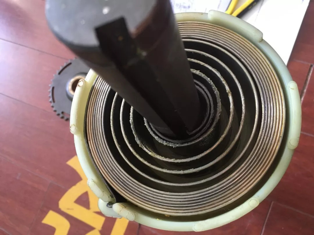
Edited Text:
Figure 1: Plane Scroll Spring
As illustrated in Figure 1, one end of the plane scroll spring is secured to the main shaft, while the other end is attached to the spring casing. During energy storage, the main shaft end of the volute spring remains stationary, and the energy storage motor or the energy storage rocker rotates the spring casing clockwise (as viewed from the left side of the mechanism; the same orientation applies throughout) via the ratchet pawl, chain, and large gear, thereby tensioning the scroll spring.
When it comes to opening and closing operations, the shell end of the scroll spring is fixed, and upon release of the tripping mechanism, the main shaft rotates clockwise under the drive of the scroll spring, outputting its stored energy.
Given that the VD4 employs a planar scroll spring, the transition between the spring's "uncharged" and "stored" states differs from most spring-operated mechanisms. It involves a gap-fixed arrangement on the scroll spring shell, facilitated by the coordination of a disk, an auxiliary cam affixed to the main shaft, and a roller mounted on the energy storage connecting rod. In simpler terms, once energy storage is completed, the roller, driven by the energy storage connecting rod, engages into a notch on the disk. Consequently, the energy storage connecting rod rotates to a specific angle, prompting the associated energy storage auxiliary contact and the energy storage mechanical indicator to switch to the "Energy Stored" state. Conversely, during the circuit breaker's closing process, the maximum radius of the auxiliary cam traverses the disk's gap, pushing the roller back to the disk's outer edge. This action drives the energy storage connecting rod back to its original angle, causing the energy storage auxiliary contact and the energy storage mechanical indicator to revert to the "Non-Energy Stored" state.
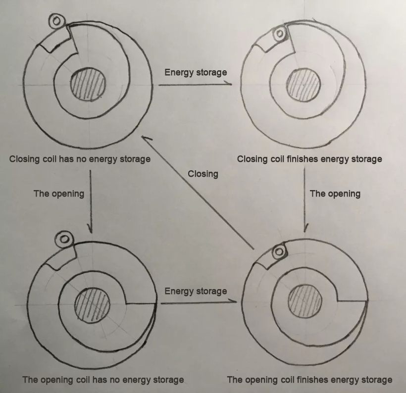
Figure 2: Schematic Diagram of Energy Storage State Transition
It is important to note that, in the case of a traditional VD4 switch that is in the open position without energy storage, a significant amount of energy remains stored within the planar scroll spring. Therefore, safety precautions must still be taken.
2. Trip Module
The trip module of the VD4 switch operating mechanism boasts a sleek and distinctive design. Despite its apparent complexity, upon dismantling and analyzing it, the entire tripping module can be broken down into three fundamental tripping structures:
The first-stage tripping structure consists of the front roller and the brake disc of the large fan-shaped plate, which functions as a specialized "detent + roller" tripping structure. The second stage comprises the large fan-shaped plate and the large half-shaft, forming a typical "half-shaft + fan-shaped plate" tripping structure. The third stage includes the opening half-shaft, the opening fan-shaped plate, the closing half-shaft, and the closing fan-shaped plate, which together constitute two sets of "half-shaft + fan-shaped plate" tripping clamp combinations.
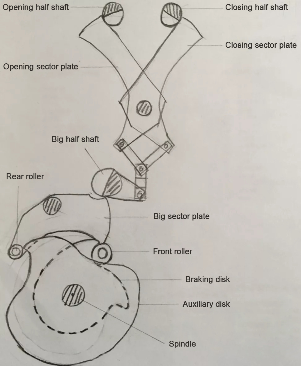
Figure 3: Structural Diagram of the Trip Module
The trip module of the VD4 switch operating mechanism serves both a holding and tripping function. Let's delve into these functions in detail.
Holding Function:
Taking the closing position as an example, once the closing action is completed, the front roller of the large fan-shaped plate falls into the corresponding slot on the brake disc. At this point, the large half-shaft is securely held in place by the pincer structure formed by the opening and closing sector plates. This prevents the front rollers of the large sector plates from being lifted, effectively locking the brake disc and maintaining the main shaft in the closing position.
Tripping Function:
Now, let's consider the tripping function using the opening action as an example. When the mechanism receives an opening command, the opening half-axis rotates clockwise through a specific angle. This movement causes the opening fan plate to lose its temporary fulcrum and rotate clockwise, disintegrating the pincer-shaped support structure formed by the opening and closing fan-shaped plates. As a result, the large half-axis rotates counterclockwise under the action of the return spring, releasing the large fan-shaped plate. The large fan-shaped plate then lifts the front roller under the action of the return spring, releasing the brake disc. The brake disc rotates clockwise under the action of the scroll spring, initiating the opening action.
During the opening process, the connecting rod on the auxiliary shaft of the opening and closing position (as shown in Figure 4) pushes the opening sector plate to reset and re-engages it with the opening half-shaft. This re-establishes the clamp-shaped support structure formed by the opening and closing sector plates and pushes the large half-shaft back to its original angle. Simultaneously, the auxiliary discs on both sides of the brake disc act on the rear rollers of the large fan-shaped plate as they rotate with the main shaft. This lifts the rear part of the large fan-shaped plate and lowers the front part, preparing it for the next locking of the front roller to the brake disc.
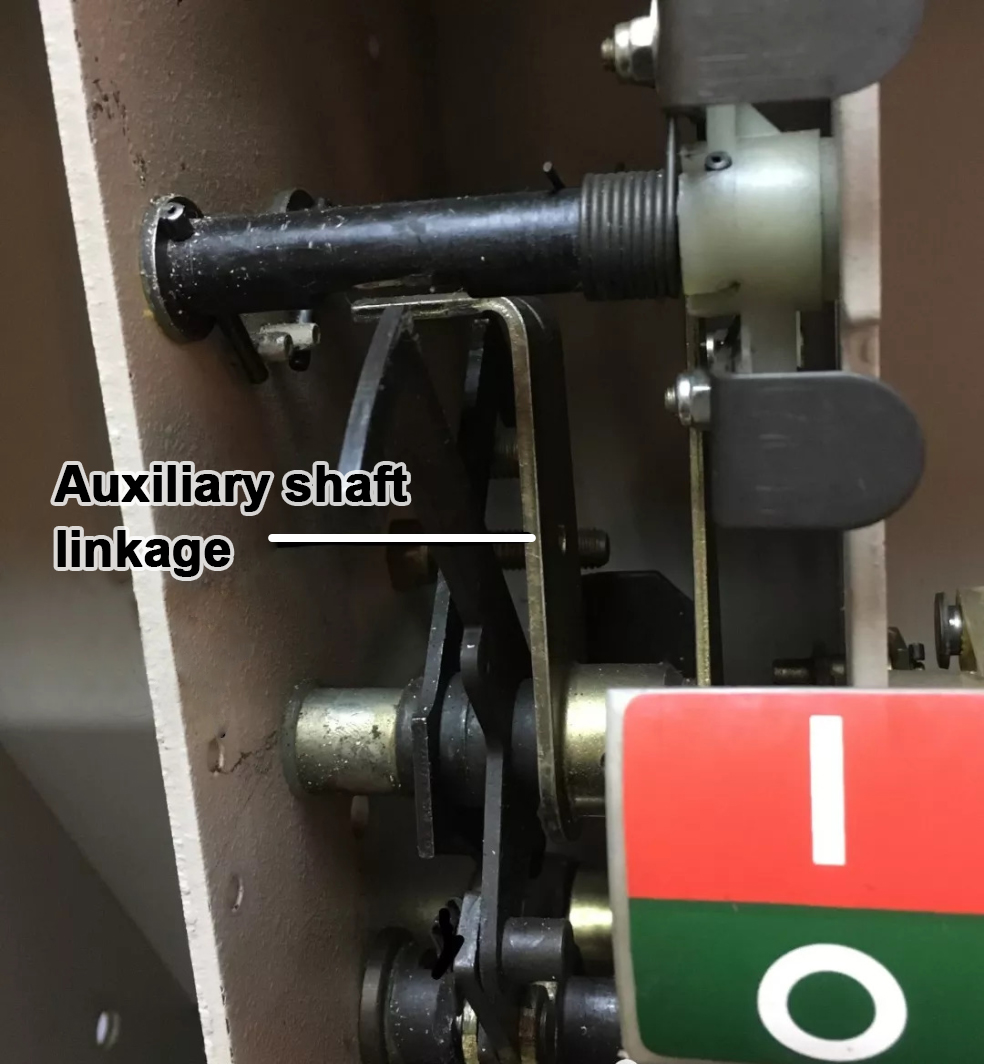
Figure 4: Opening and Closing Position Auxiliary Shaft Connecting Rod
The auxiliary shaft connecting rod plays a crucial role in the operation of the VD4 switch mechanism. It ensures the smooth transition between the opening and closing positions by connecting the opening and closing sector plates and facilitating their movement.
3. Output Module
The output module of the VD4 operating mechanism is a vital component that converts the rotational motion of the main shaft into the linear motion required for opening and closing the circuit breaker. It consists of three cam discs mounted on the main shaft and three double-arm moving links located at the bottom of the mechanism.
The double-arm moving link functions as a lever, with its fulcrum located in the middle. The front end of the lever is influenced by the cam disc on the main shaft, while the rear end is connected to the insulating pull rod of the vacuum bubble and the opening spring.
During the closing operation, the cam disc rotates with the main shaft, pressing down on the rollers at the front end of the double-arm moving link. This action lifts the rear end of the link, pushing the insulating pull rod upward and closing the dynamic and static contacts within the vacuum bubble. Simultaneously, the opening spring is compressed, storing energy for the subsequent opening operation.
Conversely, during the opening operation, the cam disc rotates in the opposite direction, releasing the rollers at the front end of the double-arm moving link. This allows the opening spring to expand, separating the dynamic and static contacts and opening the circuit.
4. Locking Function
The VD4 operating mechanism includes a comprehensive locking function that enhances safety and reliability. Here's a closer look at each of the locking features:
-
Prohibition of Closing When Handcart is in Middle Position:
- A closing locking electromagnet (Y1) is installed.
- Limit switches (S8 and S9) are connected in parallel with the closing locking electromagnet to form the closing locking circuit.
- When the handcart is in the test position or working position, either S8 or S9 connects to the closing locking circuit, charging the closing locking electromagnet and releasing the mechanical locking of the closing semi-axis.
- An auxiliary switch (S2) in the closing circuit of the circuit breaker is connected in series with the moving iron core of the closing locking electromagnet, preparing the circuit for executing the closing command.mentioned above, the measure combines mechanical locking and electrical locking, which is a comprehensive locking scheme.
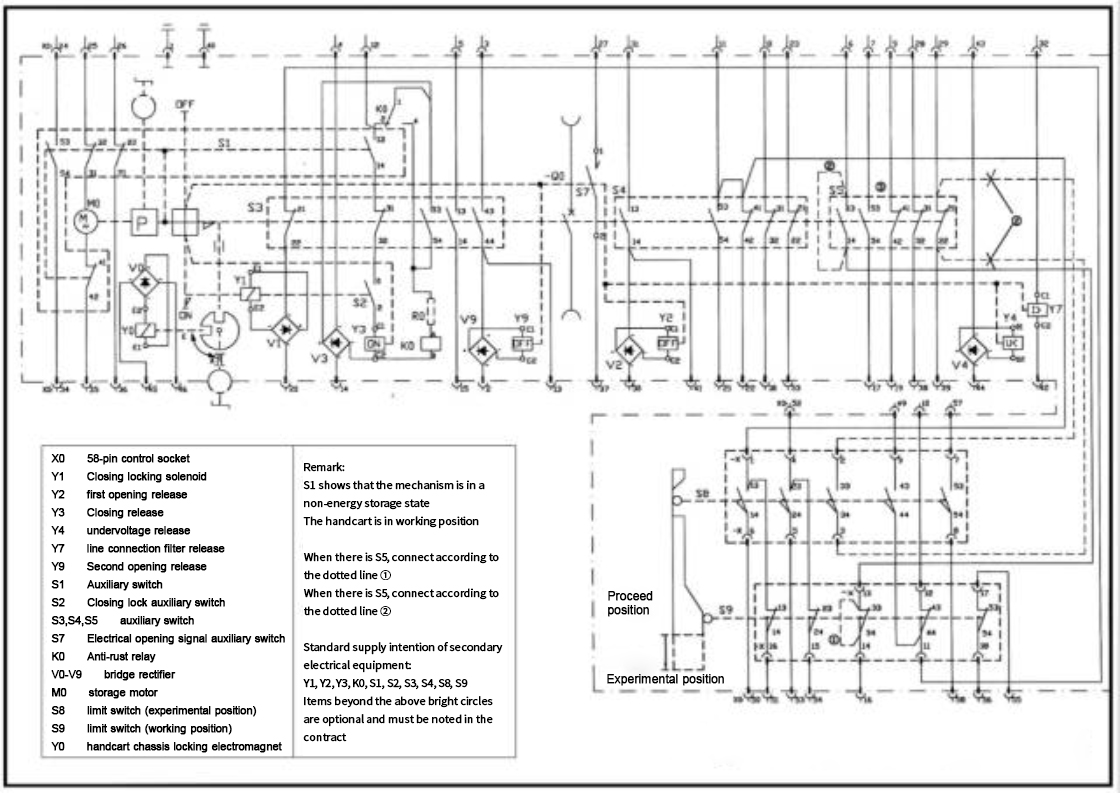
The description provided details the importance and functionality of the auxiliary switch S2 in the closing circuit of a VD4 electrical control wiring diagram for a handcart-type circuit breaker. Here's a concise summary and explanation of the key points:
Auxiliary Switch S2 in the Closing Circuit
-
Enhanced Locking Reliability:
- The auxiliary switch S2 is used in conjunction with the mechanical locking provided by the closing locking electromagnet Y1.
- This dual locking mechanism increases the reliability of the circuit breaker's locking function.
-
Prevention of Overheating and Damage:
- If S2 is not included in the closing circuit, and the circuit breaker handcart receives a closing command while in the middle position, the closing circuit would be energized.
- Due to the blocking action of the closing locking electromagnet Y1, the closing half-axis cannot rotate, preventing the circuit breaker from closing.
- This would lead to prolonged energization of the closing electromagnet, causing it to overheat and potentially burn out.
-
Auxiliary Switch Role:
- By including S2 in the circuit, it ensures that the closing electromagnet is only energized when the circuit breaker is in the correct position for closing.
- This prevents unnecessary energization and potential damage to the electromagnet.
Closing Interlock Mechanism
-
Mechanical Locking:
- The closing interlock mechanism is a purely mechanical system that uses a four-link structure composed of the circuit breaker interlock plate, interlock lever, and locking lever.
- This mechanism is established between the lead screw of the chassis car and the closing half-shaft of the circuit breaker.
-
Functionality:
- When the circuit breaker handcart is in the test or working position, the circuit breaker interlock plate in the chassis is horizontal, allowing the closing half-shaft to rotate freely.
- When the handcart is in the middle position, the interlock plate is lifted by the lead screw, causing the locking lever to engage with the plastic cam of the closing half-shaft, locking its rotation.
In conclusion, the auxiliary switch S2 in the closing circuit and the closing interlock mechanism are both crucial components that ensure the safe and reliable operation of the circuit breaker handcart. They work together to prevent unauthorized or unsafe closing operations and protect the equipment from potential damage.
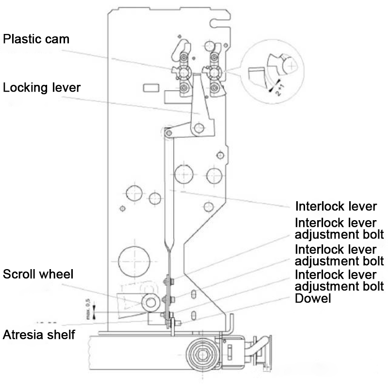
Figure 6 Closing Interlock Mechanism

The description provided gives a detailed overview of the VD4 handcart chassis components and their functions, particularly focusing on safety mechanisms and operational constraints. Here's a summary and explanation of the key points:
-
Chassis Deformation and Maintenance:
- The study revealed that chassis deformation or jamming can prevent the mechanical lock from releasing properly, leading to the burning of the closing coil.
- To prevent this, regular inspection and maintenance of related components should be conducted to ensure the chassis is in good working condition.
-
Blocking Handcart Movement When Circuit Breaker is Closed:
- The VD4 switch uses a mechanical locking mechanism to prevent the handcart from being moved in or out when the circuit breaker is closed.
- This is achieved through the cooperation between the locking frame on the interlocking plate and the front rollers of the B-phase dual-arm moving link.
- When the circuit breaker is closed, the front rollers are pressed down, creating a small gap with the locking frame. Attempting to move the handcart will cause the lead screw to push against the interlock plate, which in turn reacts on the lead screw, blocking movement.
-
Blocking Closing Switch Without Energy Storage:
- It is crucial that the circuit breaker has sufficient energy stored before it can be closed.
- Without energy storage or incomplete energy storage, the closing speed and force will decrease, potentially leading to closing failure.
- The VD4 switch uses a cooperation between the energy storage locking plate and the extension plate of the closing fan-shaped plate to block closing when there is no energy storage.
- When energy storage is complete, the roller on the energy storage connecting rod engages with the disc, allowing the circuit breaker to close normally.
In summary, the VD4 handcart chassis components include safety mechanisms to prevent improper operation, such as blocking movement when the circuit breaker is closed and preventing closing without sufficient energy storage. Regular maintenance and inspection of these components are essential to ensure the safe and reliable operation of the equipment.
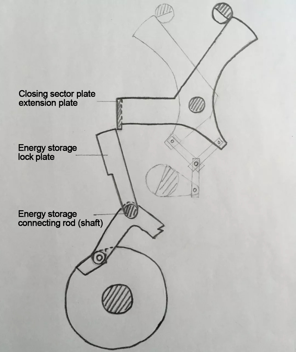
Figure 8 a Energy storage lock plate position when energy is stored

Revised Text:
Figure 8(b) illustrates the position of the energy storage lockout plate when no energy is stored.
To complement the aforementioned mechanical locking mechanism, the VD4 switch is also connected in series with the energy storage auxiliary switch S1 (as depicted in Figure 5) within the closing circuit. This arrangement enhances the electrical locking function and safeguards against potential burnout of the closing electromagnet.